Battery Charger IC ME4057 considerations
1. Power dissipation
The conditions that cause the ME4057 to reduce charge current through thermal feedback can be approximated by considering the power dissipated in the IC. Nearly all of this power dissipation is generated by the internal MOSFET-this is calculated to be approximately: PD=(VCC-VBAT ) X I BAT

This is similar (almost the same) to TP4056. Below URL is a reference to IC TP4056.
TP4056 VCC에 연결된 저항에 질문 있습니다.
대한민국 모임의 시작, 네이버 카페
cafe.naver.com
2. Set LED's resistors as 1K
This content does not appear in the datasheet. However, when the design was designed by replacing the actual resistance on the back of the LED with 100 ohms, the standby status LED did not appear even though the LED was intermittently flashing, illuminated, or fully charged. Therefore, it is better to set it at 1 kohm if possible. And there was a q&a related to this, so it would be nice to refer to.

충전회로TP4056 충전LED점멸문제
대한민국 모임의 시작, 네이버 카페
cafe.naver.com
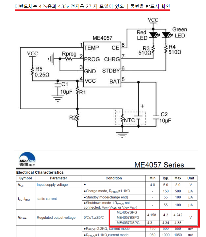
3. Consider the IC type.
If you are using a 4.2V fully charged lithium-ion battery and buy a charging IC for 4.35v, the standby LED will never turn on.
4. Boarder layout consideration


